Tab ATHENA Model > Group Output > 3D model projection
Menu:
Modeling > Analyze > 3D model projection
Toolbar:
ATH Analyze > 3D model projection
Command input:
ath_c3d_project
Creates a two-dimensional view from the selected 3D elements. The selection of the 3D elements is done by job selection or object selection.
When you call the command, the Dialog box Projects is displayed. Here you can select the objects you want to project. You will find further information on this in the section Select project.
After selecting a job, partial job, or individual parts by object selection, the following dialog box appears where you can make additional settings for the projection.
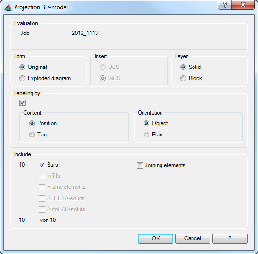
Dialog box Projection 3D model
db_ath_c3d_project
Dialog box section Evaluation
The source from which the parts come is displayed here. If the source is a job, the name of the job and the name of the partial job are displayed. If the parts were selected manually, object selection is displayed.
Dialog box section Display
Original Creates a projection in the original view.
Exploded drawing Creates a projection in exploded view.
Dialog box section Insert
UCS Inserts the projection into the current user coordinate system.
WCS Inserts the projection into the world coordinate system.
Dialog box section Layer
Solids Uses the layer of solids for the inserted block of the projection.
Block Uses the current layer for the inserted block of the projection.
Dialog box section Labeling by
Activates or deactivates the labeling of objects.
Dialog box section Contents
Position Labels the item numbers of the objects.
Tag Labels the identifiers (tags) of the objects.
Dialog box section Alignment
Object Aligns the label to the respective object.
Elevation Aligns the caption to the view in which the projection is inserted.
Dialog box section Include
By switching the respective switch on or off, you can determine which components of the 3D model are to be projected.
Bars Projects members contained in the selected 3D model.
Joining elements Projects fasteners attached to the rods.
Infills Projects fillings contained in the selected 3D model.
Frame elements Projects insert elements contained in the selected 3D model.
ATHENA solids Projects ATHENA solids contained in the selected 3D model.
AutoCAD solids Projects AutoCAD solids contained in the selected 3D model.
End of program
You terminate the command by clicking on OK. The settings in the dialog box are saved and the projection of the model is calculated. Then follows a prompt to insert it into the drawing.
If you click Cancel, the command terminates and the settings in the dialog box are discarded. No projection is inserted