At the top left there are two buttons for favorites. You will find further information on this in the section Saving and using favorites.
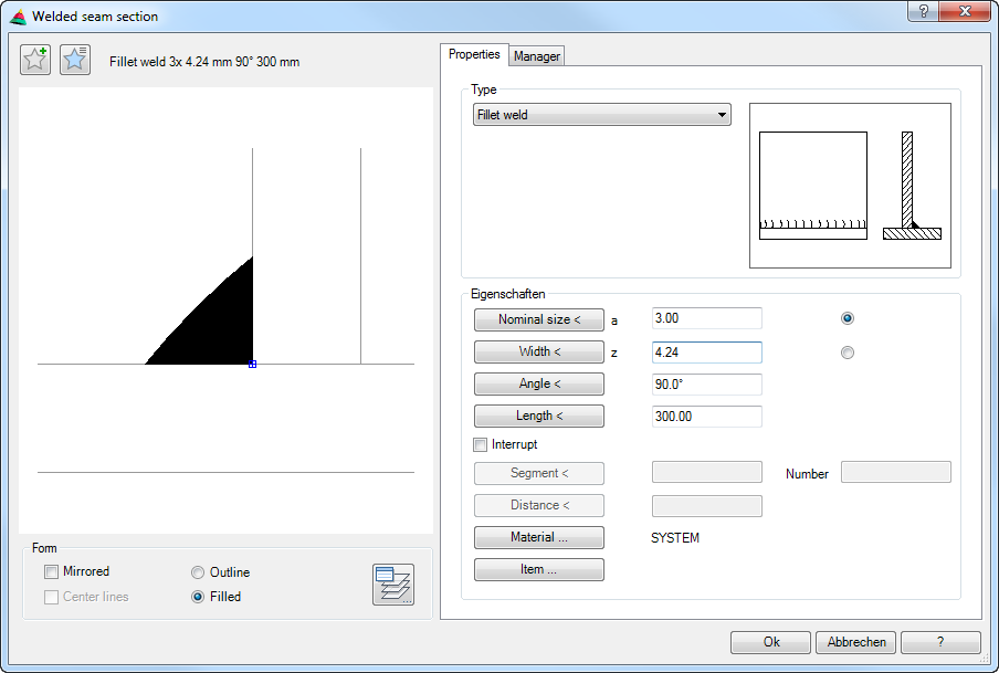
The preview is primarily intended for visual checks and shows the welded seam in cross-section with the current set properties.
Additional functions are activated by clicking in the preview with the mouse wheel. You will find further information on this in the section Object preview.
Dialog box section Display
Mirrored Creates a weld cross section that is mirrored around the Y axis.
Axes Switches centerlines on or off for symmetrical weld cross sections (e.g. point seam or line seam).
Outline Creates a welded seam section without infill.
The available display options vary depending on the weld type, so not all options are always active.
Operating section
Tab Properties
Dialog box section Type
The pick list shows all available welded seam types. Here, you select the desired welded seam.
Alternatively, you may also click on the image next to the list. This opens the Dialog box Welded-seam Symbol Overview where you may also select the required seam type.
Dialog box section Properties
Nominal size < a Defines the nominal size of the welded seam section. If you enter a nominal size, the thickness is calculated. Activating the option causes the nominal size a to be displayed when labeling. By clicking on the button, the dialog box is temporarily closed and you may specify the nominal size by specifying two points.
Thickness < z Defines the seam thickness of the welded seam section. If you enter a thickness, the nominal size is calculated. Activating the option causes the thickness z to be displayed when labeling. By clicking on the button, the dialog box is temporarily closed and you may specify it by specifying two points.
Angle < Defines the angle of the welded seam section. By clicking on the button, the dialog box is temporarily closed and you may specify the angle by specifying two points.
Length < Defines the length of the welded seam section. By clicking on the button, the dialog box is temporarily closed and you may specify the length by specifying two points.
Interrupt Creates interrupted welds. If you activate this switch, you must specify the segment length and the number of segments.
Segment < Defines the segment length of the interrupted welded seam. By clicking on the button, the dialog box is temporarily closed and you may specify the segment length by specifying two points.
Number Defines the number of welded seam segments.
Distance < Defines the spacing between the segments. By clicking on the button, the dialog box is temporarily closed and you may specify the distance by specifying two points.
The interruption (segmentation) of the weld seam influences the labeling, but has no effect on the depiction of the weld cross-section.
The available properties vary depending on the weld type, so not all properties are always active.
Item ... Opens the Dialog box Item, where you can select an item number. You will find a detailed explanation on items in the Chapter Item.
End of program
Input request
Specify insertion point or [?]:
Use the mouse or enter co-ordinates to specify the insertion point of the welded seam section.
You can change between different insertion points by repeatedly pressing the Shift+Ctrl keys.
The grips of the relevant welded seam section can be used as insertion points. The insertion point activated by Shift+Ctrl only applies for the duration of the insertion.
Specify rotated angle<0>:
Use the mouse or enter an angle to specify the rotation angle. Press the Enter key to accept the default angle.
Associated commands
• Parts labeling: You can use it to label the weld cross-section with a Welded seam symbol. The properties of the welded seam are accepted.