Tab ATHENA Model > Group Output > Generating a section from 3D
Menu:
Modeling > Analyze > Generating a section from 3D
Toolbar:
ATH Analyze > Generating a section from 3D
Command input:
ath_c3d_cross_sect
This function enables you to generate a section from 3D objects and 2D projections by specifying a sectional plane.
You can generate sections from the following objects:
• Bar assemblies
• Infills
• 2D projections of bar assemblies, standard parts, semi-finished products and free semi-finished products
• 2D projections of infills
• Frame elements
• Bar settings
When you start the command, the following appears:
Input request
Select objects:
Select the objects which are to be used for producing the section.
Select the first axis for the plane or [Points/Settings/?]:
Select the first axis of the plane. The end points of the selected axis define the first two points of the cut plane. ATHENA bar assemblies or lines can be used as axes.
Use the Option Points to define the cut plane by specifying three points.
Select the second axis for the plane or [Ybar/Xbar/Points/Undo/?]:
Select the second axis of the plane.
Use the option Ybar to use the Y direction of the previously selected bar assembly for the plane definition.
Use the option Xbar to use the X direction of the previously selected bar assembly for the plane definition.
Use the option Undo to repeat the last input request.
Specify insertion point or [?]:
Define the insertion point of the section.
Option Points
Specify first point for plane or [Objects/?]:
Define the first point of the cut plane.
Specify second point for plane or [Objects/Undo/?]:
Define the second point of the cut plane.
Specify third point for plane or [Objects/Undo/View/?]: <View>:
Specify the third point of the cut plane.
The View option determines the third point of the plane in the current view. If you set the view appropriately before generating the section (e.g. perpendicular onto the bars to be cut), you save entering a point.
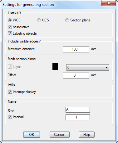
Option Settings
Dialog box Settings for section generation
db_ath_c3d_cross_sect
Dialog box section Insert in
WCS Inserts the generated section in the XY plane of the World Coordinate System.
UCS Inserts the generated section in the XY plane of the current User Coordinate System.
Section plane Inserts the generated section in the specified sectional plane.
Associative Generates an associative section which can be modified.
For associative sections the marking of the sectional plane (see further below) is a condition.
Labeling objects Labels the profiles and infills of the section.
Dialog box section Include visible edges
Maximum distance Specifies the maximum distance to the sectional plane in which visible edges of the solid of unsectioned bars and infills are displayed in section. E.g.: You are generating a horizontal section through two mullions. If a transom is located less than 100 mm below the sectional plane, its visible edges are shown in section.
Dialog box section Mark section plane
Layer The tick box activates the sectional plane marking. In the pull-down menu you can select a layer for marking.
Enlarge by Specifies the enlargement of the sectional plane marking.
The sectional plane is identified by a region and a directional system (cone). The size of the region corresponds to the enclosing rectangle of the sectioned objects plus the enlargement.
The sectional plane is a prerequisite for associative sections.
Dialog box section Infills
Interrupt display Generates infills with interrupted display (right and left section instead of complete infill).
Dialog box section Name
Start Defines the section designation. The section designation is incremented if the Interval tick box has been activated.
Interval Activates incrementing of the section designation. You can define the interval in the input field.
E.g.: If you enter A at the start and the interval 1, the first section is designated A-A, the second B-B, etc.
Note
• Draw, where applicable in advance, two lines defining a sectional plane. You can select them via object selection.
• Note that object projections on a plane located obliquely in space may be displayed distorted.