Defines and modifies elements (window and door elements). Elements can be saved as library objects.
Use the command Apply element to use saved window and door elements in the drawing.
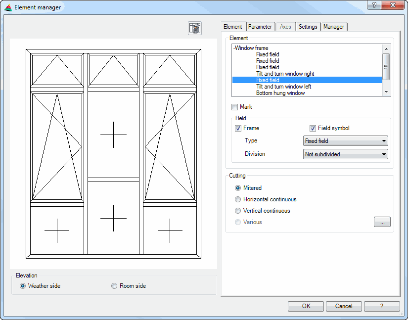
Dialog box Element
db_ath_elem
Display section
On the left side the dialog box contains a preview of the defined element elevation. Active elements are optionally marked in color. The preview is used for the visual check; it changes when you change tabs.
Additional functions are activated by clicking in the preview with the mouse wheel. You will find further information on this in the section Object preview.
All dimensions are saved relatively and are determined only on insertion of the element by specifying the frame dimension.
The size of the element in the preview cannot be changed in the dialog box. If a larger element is needed in the preview, you can select a larger outline with the command Element and cancel the command. The last dimensional entry determines the size of the element in the preview.
Dialog box section Elevation
Weather side Creates the weather side or outer side of an element.
Room side Creates the room side or inner side of an element.
Operating section
On the right side of the dialog box there is the operating section with the tabs:
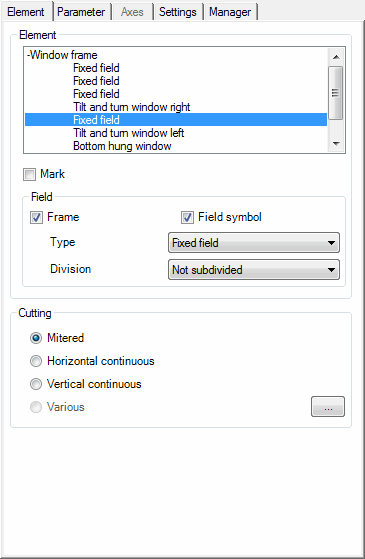
List Displays the available objects of an element. Here, select the object which you want to modify.
You can also select the object directly in the preview. Click the appropriate object with the left mouse key.
Mark Displays the marked object in the preview colored or not.
Dialog box section Field
Frame Switches the frame of the selected object on or off.
Symbol Switches the tilt and turn symbol of the selected object on or off.
Type Defines the window or door type for the selected object.
Division Defines how the selected object is divided up.
Dialog box section Cutting
Mitered Cuts the profiles of the selected object for mitering.
Horizontal continuous Cuts all profiles of the selected object horizontally continuous.
Vertical continuous Cuts all profiles of the selected object vertically continuous.
Various Carries out the profile cuts differently. Click the button [...] to individually define the blanks for the profile cuttings.
[...] Opens the Dialog box Cutting, where you can individually define the profile cuttings for the selected object.
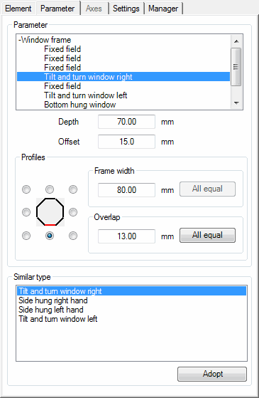
Tab Parameter
db_ath_elem_parameter
Dialog box section Parameter
The frames and sashes of the element are listed in a tree structure. If you mark an object here, its properties are shown further down in the dialog box and can be adapted.
Depth Defines the profile depth.
Offset Defines the offset.
These values are relevant when you produce a section through the element.
Dialog box section Profiles
Here you can define the frame width and the overlap for the selected element. You can specify the dimensions just for single profiles or for all profiles.
To specify the dimensions for a profile you can specify the relevant position of the octant (top, top right, right, bottom right, bottom, bottom left, left, top left) using option buttons:
Frame width Defines the frame width for the profile in the marked octant.
All equal Accepts the specified frame width for the profiles in all positions.
Overlap Defines the overlap for the profile in the marked octant.
All equal Accepts the specified overlap for the profiles in all positions.
Dialog box section Similar type
Displays a list with similar element types.
Here, you can select the element types for which you want to use the set parameters as default. Multiple selection is possible with a pressed CTRL or Shift key.
Adopt Accepts the set parameters for the selected element types.
This default is saved for the duration of the drawing session.
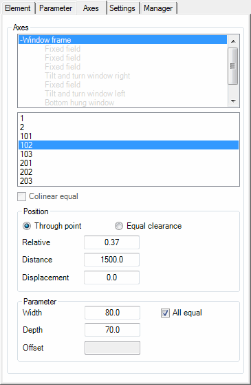
Tab Axes
db_ath_elem_achsen
Dialog box section Axis
The list displays the available axes.
For an element with three horizontal and three vertical elements the axes are listed as follows:
• 1, 2: Vertical axes from left to right.
• 101, 102, 103 and 201, 202, 203: Horizontal axes, in each case from left to right and from bottom to top.
From the list select the axis whose settings you want to change. The selected axis is shown red in the preview.
You can also select the axis directly in the preview. Click the appropriate axis with the left mouse key.
Colinear equal Causes identical unit spacing for axes is used in alignment. Deactivate this tick box if you want to set different unit spacings.
Dialog box section Position
Through point Activates the axial displacement through a defined point. This tick box releases input fields where you can define axial displacement.
Equal clearance Sets equal clearance dimensions for all axes.
Relative Defines the ratio of the fields separated by the axis. For example 0.5 for equally large fields (gives a central axial position) or 0.75 for a field ratio of 3/4 to 1/4. If you enter a relative value, the absolute distance is calculated automatically.
Distance Defines the absolute distance of the axial displacement. When you change this value, the relative value is automatically calculated.
Displacement Defines the axial displacement starting from the defined distance.
The starting point of the axial displacement is left for vertical axes and below for horizontal axes.
Dialog box section Parameter
All equal Uses the entered dimensions for all profile axes.
Width Specifies the width of the axis.
Depth Specifies the depth of the axis.
Offset Specifies the offset of the axes.
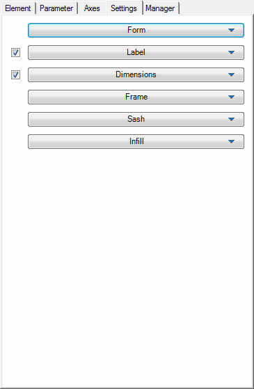
Tab Settings
db_ath_elem_einstellung
Defines further display options and dimensions of the profiles and infills. These parameters are used for the display and when generating sections.
The Settings tab includes the following drop-down menus:
The preview shows a window and a door element (profiles and infills in each case) in the section. The elements of the active drop-down menu are shown in red. Dimensional changes can therefore be immediately tracked.
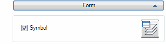
Drop-down menu Form
db_ath_elem_einstellung_darstellung
Symbol Switches the tilt and turn symbol of the element on or off.
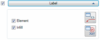
Opens the dialog box Label infill. You will find further information on this in the Chapter Label format.
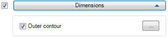
Drop-down menu Dimensions
db_ath_elem_einstellung_bemassung
Outer contour Switches the labeling of the outer contour on or off.
[...] Opens the Dialog box Dimension options, where you can define in which way the element is to be dimensioned. You will find a detailed description of the Dimension options dialog box in the chapter Dimensioning options.
Drop-down menu Frame
db_ath_elem_profile_rahmen
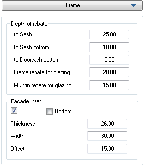
Dialog box section Depth of rebate
to sash Defines the rebate depth of the frame profile to the sash.
to sash bottom Defines the rebate depth of the frame profile to the sash bottom.
to door sash bottom Defines the rebate depth of the frame profile to the door sash bottom.
Frame rebate for glazing Defines the glass rebate of the frame profile.
Muntin rebate for glazing Defines the glass rebate for the muntin.
Dialog box section Facade clamping
Activates the clamping frame profile for the window frame. Additional input fields are released, where you can specify the additionally required dimensions. The bottom clamping frame must be activated separately.
Bottom Activates a clamping frame for the frame profile bottom.
Thickness Defines the clamping thickness.
Width Defines the width of the clamping section.
Offset Defines the distance from the clamping section to the front edge of the frame.
Drop-down menu Sash
db_ath_elem_profile_fluegel
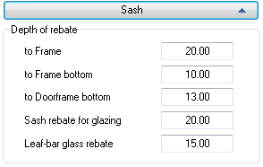
Dialog box section Depth of rebate
to frame Defines the rebate depth of the sash profile to the frame.
to frame bottom Defines the rebate depth of the sash profile to the frame bottom.
to door frame bottom Defines the rebate depth of the sash profile to the door frame bottom.
Sash rebate for glazing Defines the glass rebate of the sash profile.
Glass rebate for sash muntin Defines the glass rebate for the sash muntin.
Drop-down menu Infill
db_ath_elem_profile_fuellung
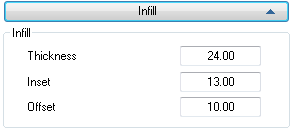
Dialog box section Infill
Thickness Defines the thickness of the infill.
Inset Defines the inset of the infill in the surrounding profiles.
Offset Defines the distance of the front edge of the infill to the front edge of the surrounding profiles.
Tab Manager
You will find a detailed description of the functions of the manager in the Chapter Management of objects.
End of program
OK closes the dialog box and the settings are saved.
Cancel closes the dialog box and the settings are discarded.