Here, you manage the system layer used by ATHENA as well as the layer and hatch assignments to the various objects and object constituent parts.
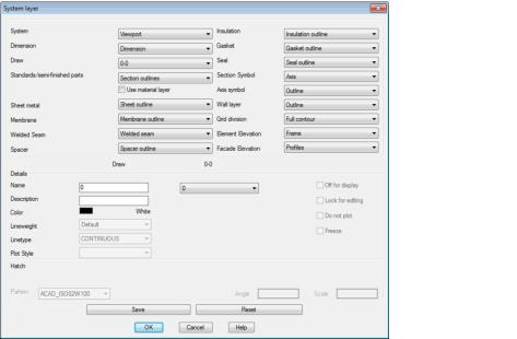
Dialog box System layer
db_ath_layer_sys
Dialog box section Object
From the pick lists of the various groups you can select the object type whose layer or hatch properties you would like to change. The current layer properties of the selected object are displayed in the Dialog box section Details. The current hatch properties are displayed in the Dialog box section Hatch. Hatch properties are only displayed once you have selected the infill of the respective object.
Note: ATHENA uses the assigned layer and hatching as the system properties for the relevant objects. When you assign a material to an object in its generating dialog field, the material properties are used instead of the system properties.
System layers or system hatching and their application
• System
– Viewport: Layer for viewport
– Viewport marking: Layer for viewport marking in the model space
– Slice plane: Layer for the slice plane on which 3D bars are cut off.
– Auxiliary Lines: Layer for auxiliary lines
• Dimensions
– General dimensioning: Layer for linear and angular dimensioning
– Dependent on interrupted dimensions: Layer for dependent (computed) interrupted dimensions
– Definition of interrupted dimensions: Layer for defined interrupted dimensions
– Levels: Layer for horizontal and vertical levels
– Center lines, axes: Layer for axes
– Labeling: Layer for leaders, part labels, results tables and other texts
• Drawing
– 0-0 to 7-1: General drawing layer
• Standard parts/semi-finished products
– Section outlines: Layer for semi-finished products and standard part profiles
– Miscellaneous parts: Layer for other standard parts (screws, plugs, etc.)
– Hidden lines: Layer for hidden lines of the standard parts (e.g. holes in panels) as well as for copied objects and objects displayed as covered.
– Axes: Axes layer
– Thread lines: Layer of thread lines for screws
– Infill/hatching: Layer and hatching for standard parts
– Contour edge: Layer for tangential transitions for standard parts
– Solids: Layer for standard solid parts
• Sheet metal
– Sheet outline: Layer for the sheet outline
– Sheet infill: Layer and hatching for the sheet
– Infill for core layer: Layer and hatching for core layer with composite panels
– Solids: Layer for sheet solids
– Fold downwards: Layer for fold lines with sheet developments
– Fold upwards: Layer for fold lines with sheet developments
– Rolled edge: Layer for rolled edges with sheet developments
– Coating: Layer for coating lines with sheet metal sections
• Membrane
– Membrane outline: Layer for membrane outline
– Membrane infill: Layer and hatching for the membrane infill
• Welded seam
– Welded seam: Layer for the welded seam
• Spacer
– Spacer outline: Layer for the external outline of the spacer
– Spacer infill: Layer and hatching for the spacer
• Insulation
– Insulation outline: Layer for the insulation boundary
– Insulation infill: Layer and hatching for insulation
• Gasket
– Gasket outline: Layer for the external outline of the gasket
– Gasket infill: Layer and hatching for the gasket
• Seal
– Seal outline: Layer for the external outline of the seal
– Seal infill: Layer and hatching for the seal
– Infill sealing cord: Layer and hatching for sealing cord
• Section symbol
– Axes: Layer of the lines of the section symbol
– Symbol: Section symbol layer
• Axis symbol
– Outline: Layer for the external outline of the axis symbol
– Glazing axis: Layer for glazing axis
– Infill/hatching: Layer and hatching for the symbol
• Wall layer
– Outline: Layer for the external outline of the wall layer
– Infill/hatching: Layer and hatching for the wall layer
• Grid division
– Full contour: Layer for the complete (unprocessed) contours
– Trimmed contour: Layer for the processed contours
– Infill/hatching: Layer and hatching for the grid elements
• Element elevation
– Frame: Layer for the frame
– Sash: Layer for the sash
– Field symbol: Layer for the field symbol (tilt and turn symbol)
• Facade elevation
– Profile: Layer for the profiles
– Hidden: Layer for the hidden profiles
– Center lines: Layer for center lines
Dialog box section Details
db_ath_layer_sys_details
The active object type is shown above the section Details. Here ATHENA displays the layer properties for the selected object type. You can adapt the layer properties to your own requirements.
It is not possible to change the layer properties if the corresponding layer is already present in the drawing. In this case use the AutoCAD layer properties manager.
Name To use a new layer name, write it into the Name input field. You can also assign an existing layer to an object type. To do this, select a layer from the pick list.
Description Defines a layer description. The layer description is additional information which is also displayed in the AutoCAD layer properties manager.
Color To change the layer color, click the color area and select a new color.
Lineweight To change the lineweight of the layer, choose a lineweight from the drop-down menu. We recommend that you use the default lineweight.
Line type To change the line type, select a new line type from the drop-down menu.
Plot style To change the plot style, select a new plot style from the list. This drop-down menu is deactivated when you are using color-dependent plot styles (of color).
Off for display Switches the layer off or on.
Lock for editing Locks or unlocks the layer.
Do not plot Defines whether the layer is plotted or not
Freeze Freezes or thaws the layer.
Dialog box section Hatch
db_ath_layer_sys_schraffur
The active object type is displayed above. Here ATHENA displays the hatching properties for the selected object type. You can adapt the hatching properties to your own requirements.
Pattern To change the pattern of the system hatching, select a new pattern from the list.
Angle Enter a new angle in the input field Angle to alter the hatching angle.
Scale Enter a new scale factor in the input field Scale to alter the hatching scale.
When you click the Save button, the current settings are saved and loaded as default into new drawings.
ATHENA saves these settings in the file cpl_layer.dex. When you click the Reset button, the previously saved settings are restored.
If you have loaded the layer via the Design environment, when saving you can select whether the standard settings or the settings of the design environment are to be saved.
Click OK to close the dialog box. If you have not clicked the Save button, ATHENA saves the settings for the duration of the drawing session and returns to the Dialog box ATHENA options.
Note
• After termination of the dialog box, use the command Load layer to activate the new layer properties in the drawing.
• You will find further information about layers in your AutoCAD documentation.