ATH Sheet metal > Sheet metal section ATHENA Drawing > Sheet metal section
Command input:
ath_sheet_cs
With this function you create sheet metal sections or cross sections of composite panels. Similar to polylines, they can be changed with grips or by stretching. There are various construction possibilities available for creating the cross section.
Dialog box Sheet metal section
In the dialog box you will find on the left side the display section with the dynamic preview. On the right side you can see the tabs Properties, Coating, Termination, Regions and Manager.
db_ath_blec_schnitt
Display section
At the top left there are two buttons for favorites. You will find further information on this in the section Saving and using favorites.
The preview is primarily intended for visual checks and shows the part with the set properties.
Dialog box section Form
Outline Creates a sheet metal section without infill.
Lined Creates a lined sheet metal section.
Hatched Creates a sheet metal section with hatched infill. The material-dependent hatching is used.
Hatch core layer Turns the hatch infill of the core layer of the composite panel on or off. This option is only shown if composite panels have been selected.
Normal Using the option Normal you create a sheet metal section in that you specify the scale, wall thickness, limb lengths and angles by coordinates.
Fit With the option Fit you create a sheet metal section by clicking on snap points.
Polyline With the option Polyline you convert a polyline into a sheet metal section.
Operating section
Tab Properties
Sheet metal Activates the sheet metal properties.
Composite panel Activates the composite panel properties.
Dialog box section Properties of sheet metal
db_ath_blec_schnitt_blech
Sheet thickness Defines the thickness of the sheet metal.
Inner bending radius Defines the inner bending radius. The bending radius at this point can only be changed when the development occurs according to the neutral fiber. Otherwise the radius set in the bending table is used.
Distance of crimped edge Defines the distance between the edge of the sheet and the crimped edge.
Fold Shows the folding tables which have been assigned to the material. Here you can select a table with bending allowances, so that the correct development for the folded semi-finished product can be calculated. Optionally, here you can also choose development according to the neutral fiber and specify the bending radius in the appropriate input field.
The partial length of the bend is corrected when calculating the development according to the neutral fiber. The correction factor (k factor) according to DIN 6935 depends on the bending radius and the sheet thickness and must in each case be calculated or read from a graph.
Item Opens the Dialog box Item, where you can select an item number. You will find a detailed explanation on items in the Chapter Item.
Dialog box section Composite panel properties
db_ath_blec_schnitt_alucobond
List Shows the available manufacturers and their products in a tree structure. Here you can select the required manufacturer with the mouse. Closed branches in the tree structure are identified with +. Open branches are identified with -.
Thickness Defines the thickness of the composite panel.
Groove Defines the groove for folds on the composite panel. There are various grooves and shapes available depending on the type of panel.
[...] Opens the Dialog box Routing folding. Here you will find further technical information on the selected groove.
Item Opens the Dialog box Item, where you can select an item number. You will find a detailed explanation on items in the Chapter Item.
Layers Here the thicknesses of the inner and outer covering layers are shown and also the core layer.
Tab Coating
db_ath_blec_schnitt_beschichtung
Distance of coating line Activates the replacement of the default distance of the coating line. In the input field you can define the distance of the input field to the sheet.
Area Switches the coating line on for the viewed side.
Area Switches the coating line on for the opposite side.
Face side Switches the coating line on for the face side.
Surface Activates a surface specification for the area.
If you specify the coating lines for both areas, you can specify a dedicated surface for each area. For example, an RAL color for the upper side and an anti-drumming coating for the lower side of the sheet.
If you switch on the coating line for the face side, only one surface specification is possible.
The surface specification is output during labeling.
If you use a sheet with surface specification for a sheet development, the area of the coating is also labeled as well as the surface designation.
[...] Opens the Dialog box Surface manager, where you can select a surface and assign it to the area. You will find further information in the section Surface manager.
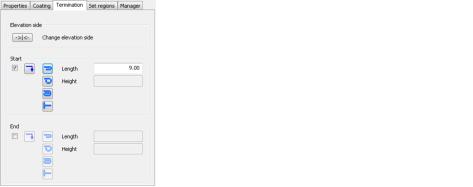
Tab Termination
db_ath_blec_schnitt_abschluss
Dialog box section Elevation side
Change elevation side Changes the elevation side. This is particularly interesting for composite panels, because they are milled on one side.
Dialog box section Start
The tick box activates the termination at the start of the sheet metal section.
Changes the direction of the fold for the selected termination fold.
Defines a crimped edge as termination.
Defines a rolled edge as termination.
Defines a rolled edge with fold as termination.
Defines an interrupted termination.
Length Defines the length of the terminating fold. This option is only available for the crimped edge and the rolled edge with fold.
Height Defines the height of the terminating fold. This option is only available for the rolled edge and the rolled edge with fold.
Dialog box section End
The tick box activates the termination at the end of the sheet metal section.
Here you can change the region settings. They are only available for composite panels.
Item only Only shows the composite panels to which an item number has been assigned.
Region Lists all available regions.
Include Includes the marked region in the display. A + (plus) is placed in front of the included regions.
Exclude Removes the marked region from the display. A - (minus) is placed in front of the excluded regions.
Tab Manager
You will find a detailed description of the functions of the manager in the Chapter Management of objects.
End of program
When you click OK, the dialog box is terminated. An input request follows depending on the type of construction selected. The input requests for sheets and composite panels are identical.
You can terminate the Dialog box Sheet metal section directly after calling the command by pressing the Enter key to access the input request. In this way you have the possibility of very quickly creating several sheets with identical properties.
E.g.: You have just created a sheet with certain properties. Now press the Enter key twice (once to repeat the sheet cross-section command and a second time to terminate the dialog box immediately) and draw a further sheet with the same properties.
Input requestNormal type of construction
Specify starting point of the sheet metal section or [?]:
The wall thickness is produced centrally to the sheet metal section with the option Central.
Specify elevation side or [Undo/?]:
Click on the side which is to be defined as the elevation side. This input request only appears for composite panels, because these are milled on the opposite side.
Specify next point or [Angle/Direction/Length/Crimped edge/Undo/?]:
Specify the next point of the sheet metal section.
With the Option Angle you can specify a fold angle. Further input requests follow.
With the Option Crimped edge you can specify a crimped edge. Further input requests follow.
This input request is repeated until you terminate the routine by entering Enter.
Option Direction
Specify direction or [Length/Undo/?]:
Point out the direction with the mouse.
Specify limb length or [Direction/Undo/?]:
Point out the length of the sheet limb with the mouse or enter a length.
With the option Direction you can correct the direction.
Specify side for wall thickness or [Undo/Central/?] <Central>:
The wall thickness is produced centrally to the sheet metal section with the option Central.
Some queries are repeated until you input Enter to terminate the program.
ath_blec_schnitt_normal
Sheet metal section option Normal
Input requestFit type of construction
The input requests for the Fit type of construction are mostly identically with those of the Normal type of construction. The only difference is that you can specify the wall thickness anew for each sheet limb.
ath_blec_schnitt_einpassen
Sheet metal section, Fit option
Input requestPolyline type of construction
Select Polyline or [?]:
With the mouse, select the polyline from which a sheet metal section is to be created. With the option ? you call the help.
Specify side for wall thickness or [Central/?] <Central>:
With the mouse click on the side on which the wall thickness of the sheet limb is to be built up.
The wall thickness is produced centrally to the sheet metal section with the option Central.
Delete polyline [Yes/No/?] <Yes>:
With the option Yes you delete the existing polyline.
The polyline is retained with the option No.
Note
• You can modify sheet metal sections with grips or with the AutoCAD command Stretch.
• Double click on the sheet metal or use the command Modify object, in order to change the properties (e.g. thickness) of a sheet metal cut.