With this command you can create profiled sheets (trapezoidal or corrugated sheets). There is a selection of various manufacturers and their products.
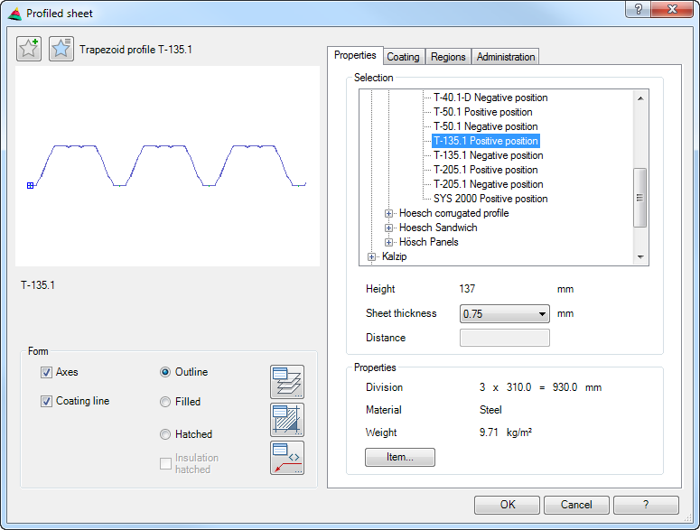
Dialog box Profiled sheet
In the dialog box you will find on the left side the display section with the preview. On the right side you can see the operating section with the tabs Properties, Coating, Regions and Manager.
db_ath_trapez
Display section
At the top left there are two buttons for favorites. You will find further information on this in the section Saving and using favorites.
The preview is primarily intended for visual checks and shows the part with the set properties. You will find further information about the dynamic preview in the section Object preview. The designation of the displayed profiled sheet is located below the preview.
Dialog box section Display
Axes Turns screwed-joint axes on or off.
Coating line Represents the coating line of the profiled sheet when a surface has been assigned.
Outline Generates a profiled sheet without infill (only external outline).
Filled Generates a fully filled profiled sheet.
Hatched Creates a profiled sheet with hatched infill. As standard, the material-dependent hatching is used. You can change the hatch pattern by clicking on the Hatched button.
Insulation hatched Hatches the insulation layer as well as the joint gaskets on sandwich elements. This tick box is only available with profiled sheet of the type Sandwich.
The current hatch pattern of the Insulation is used for the insulation layer (not the infill, i.e. wavy or zig-zag lines). You can change the hatch pattern by clicking the Hatched button in the Dialog box Insulation and setting the desired hatch pattern there.
The current hatch pattern of the Gasket is used for the joint gaskets. You can change the hatch pattern by clicking the Hatched button in the Dialog box Gasket properties and setting the desired hatch pattern there.
List Shows the available manufacturers and their products in a tree structure. Here, select the desired product from the relevant manufacturer using the mouse. Closed branches in the tree structure are identified with +. Open branches are identified with -.
Optionally, you can navigate through the list with the keyboard arrow keys. Using the Up/Down arrow keys, you can navigate a step forwards or back. Right arrow opens a branch, Left arrow closes it.
Height Specifies the height of the current profiled sheet.
Sheet thickness Determines the material thickness of the selected sheet. Only the available material thicknesses of the relevant type are offered.
Distance Defines the spacing between two profiled sheets. Thus, the distance between profile sheets can be increased to compensate, for example, tolerances. The distance input is only possible with profile sheet types, which are pushed into each other without interlocking.
The distance size is not limited by the program and is left open to the discretion of the user.
Dialog box section Properties
Displays the properties of the defined product.
• Division: Profiled sheets can be supplied with certain divisions and profile widths. The width of the inserted profiled sheet is always divisible by the specified division. When the width is greater than the specified profile width, profile joints (overlaps) are automatically created.
• Material: Here, the material is shown from which the profiled sheet is produced. Also with sandwich elements only the material of the sheet is shown.
• Weight The weight is given in kg/m². Materials are not recorded for all products
Item Opens the Dialog box Item, where you can select an item number. You will find a detailed explanation on items in the Chapter Item.
Tab Coating
db_ath_trapez_beschichtung
Dialog box section Surface
A and B Activates a surface specification for side A or B.
Normally, the A side is the face side which is coated in color, whereas the B side as the back side is given a protective lacquer.
Ask the manufacturer which surfaces are available for the relevant side.
The surface is shown as a coating line if activated. In addition, it is also output during labeling and analyzed in the list.
Tab Regions
db_ath_trapez_bereiche
Item only Only shows the profiled sheets to which an item number has been assigned.
Region Lists all available regions. Here, using tick boxes, you can control from which regions the products are to be displayed.
Tab Manager
You will find a detailed description of the functions of the manager in the Chapter Management of objects.
End of program
The dialog box is closed with OK and you can insert the selected profiled sheet into the drawing. The following procedure is used:
Input request
Specify start point:
Use the mouse or enter coordinates to specify the start point of the profiled sheet.
Specify the end point:
Use the mouse or enter coordinates to specify the end point of the profiled sheet.
Specify the side:
Using the mouse or by entering coordinates specify the side on which the profiled sheet is to be produced.
The profile sheet is now created in the drawing, whereby contiguous profile sheets are grouped. Although each profile sheet of the group is a single part, only the first and last sheet of the group has a handle for stretching. Use “Group Explode” to break up the grouped profile sheets into individual parts.
Note
• To change the properties (e.g. thickness) of a profiled sheet, use the command Modify object or double click on the profiled sheet with the mouse.
• Use Parts labeling to label the profiled sheet with a leader.
• Profiled sheets can be shortened at any point with the command Slice objects. After shortening, the profiled sheet can no longer be processed with grips (stretched).
• Sheets of a group can be broken into single profile sheets with “Group Explode”.