Tab ATHENA > Group Drawing aids > Arrange viewports
Menu:
ATHENA > Viewport > Arrange viewports
Toolbar:
ATH Viewport > Arrange viewports
Command input:
ath_vp_deta
Places a display window or multiple horizontally or vertically arranged display windows in a selected layout.
The sections for the display window are defined in the model area. Optionally, the display window may be synchronized with the model sections.
When you execute the command, the following dialog box is displayed:
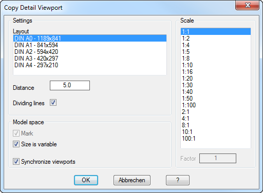
Dialog box Copy Detail Viewport
db_ath_vp_deta_masstab
Dialog box section Settings
Layout Defines the layout in which the viewports are produced.
Distance Defines the spacing between the viewports.
Dividing lines Turns dividing lines between the viewports on or off.
Dialog box section Scale
Specifies the scale of the viewport. You may select the desired scale here. The factor input field displays the scale factor of the selected scale. You will find further information about scales and their application in the AutoCAD documentation.
Dialog box section Modeling section
Mark Marks the position of the viewports in the modeling section.
Size is variable Creates display windows of different sizes. If you enable this switch, you may specify the size for each display window separately. For superimposed sections, the height is variable, for adjacent sections, the width is variable.
Synchronizing display windows Creates a display window that you can synchronize with the model sections. The model sections must be marked; therefore this option may not be switched off.
If the marking of the section in the model area is moved, the display window content in the layout changes accordingly.
Resizing the display window in the layout resizes the marking in the model space.
When you click OK, the dialog box is closed. ATHENA changes to the specified layout and the input request follows:
Input request
Specify detail
Specify first corner or [?]:
Specify the first corner point of the detail which is to be displayed in the first viewport.
With the option ? you call the help.
Specify detail
Select second corner or [?]:
Specify the diagonal corner point of the first detail. The size of the rectangle which you then specify defines the size of the first viewport.
Specify next detail
A rectangular marker now hangs on the crosshairs. Place these in the middle of the next detail. Optionally, you can still adjust the size of the section. In this case, further queries for sizing follow.
Enter width or [B] <x.x>:
Define the width of the segment with the mouse or by entering a numerical value. This prompt appears when the selected section is placed to the right or left of the first section.
Enter height or [H] <x.x>:
Define the height of the segment with the mouse or by entering a numerical value. This prompt appears when the selected section is placed above or below the first section.
These prompts are repeated. Press Enter after you have specified all the sections.
ATHENA now activates the selected layout, where you can place the display window:
Specify insertion point:
Specify the insertion point of the viewports.
You can change between different insertion points by repeatedly pressing the Shift+Ctrl keys.
Insert points are the four vertices and the center of the enclosing rectangle of all display windows. The insertion point activated by Shift+Ctrl only applies for the duration of the insertion.
Note
• The display windows are locked and pasted on a preset layer.
• The model area marking and the dividing lines between the display windows, if any, are also created on a preset layer.
• The layer settings for all elements may be adjusted in Dialog box System layer. You will find information about this in the chapter Layer.
Synchronization of display windows with model space markings:
A synchronization of the display window in the layout with the marking of the sections in the model area takes place only if the corresponding switches in Dialog box Copy Detail Viewport have been activated.
In this case you may move the section markings in the model area to change the contents of the display window in the layout.
Markings of adjacent sections are always moved together in the vertical direction, even if not all markings have been selected. In the horizontal direction, the markers may be moved independently of each other. Thus, the distance between the sections is changeable.
With markings of superimposed sections, it behaves vice versa.
Resizing of the display windows is only allowed in the layout. After resizing the display window, the section shown is reoriented in the center. The size of the corresponding marker in the model area will be adjusted accordingly.
When deleting markings from model area sections, the associated display windows lose their associativity and may no longer be synchronized.