Tab ATHENA > Group Drawing > Sheet metal processing
Menu:
ATHENA > Sheet metal > Sheet metal processing
Toolbar:
ATH Sheet metal > Sheet metal processing
Command input:
ath_easy_sheet
With this program you can create, process and output the facade sheets. In a dialog box with various tabs you can define all the properties, such as dimensions, folds, joints and corner variants as well as additional processes. Then you can insert the result as a 3D model, development or sectional view in the drawing or generate DXF data.
The display section shows a schematic preview of the currently described sheet or parts of it. The preview is used for a simple visual check and for the selection of elements for further processing.
Dialog box section Display section
db_ath_easy_sheet_darstellungsbereich
Changing the view
Using the buttons on the left side you can switch between various permanently defined views of the sheet model. Apart from the normal and isometric views, the preview of the schematic development is possible at any time.
Primary surface This shows the active area of the sheet viewed from above and the active area in the processing mode (Tab Processing).
View from above Shows the complete sheet as viewed from above. Parts of the sheet may be hidden.
View from the left Shows the complete sheet as viewed from the left. Parts of the sheet may be hidden.
View from the right Shows the complete sheet as viewed from the right. Parts of the sheet may be hidden.
View from the front Shows the complete sheet as viewed from the front. Parts of the sheet may be hidden.
View from behind Shows the complete sheet as viewed from behind. Parts of the sheet may be hidden.
Isometric view SW Shows the complete sheet as an isometric view from the southwest. Parts of the sheet may be hidden.
Isometric view SO Shows the complete sheet as an isometric view from the southeast. Parts of the sheet may be hidden.
Isometric view NO Shows the complete sheet as an isometric view from the northeast. Parts of the sheet may be hidden.
Isometric view NW Shows the complete sheet as an isometric view from the northwest. Parts of the sheet may be hidden.
Development Shows the complete sheet in the developed view.
Dynamic change of viewing angle In addition to the currently set view, it can be swiveled within a range of 45° on either side. The step increment of the slide control is 1° on the scale. You can also operate the activated slide control with the mouse wheel. Exceptions for this function are the views primary surface, plan view and development.
Other methods of changing the view are offered by a mouse click in the preview. A small crosshair is displayed instead of the mouse pointer. Similar zoom functions are made available as in a drawing.
Dynamic zoom To be able to view elements better, the distance to the sheet can be changed. This occurs with the aid of a forwards and backwards movement of the mouse wheel. Here, the distance is changed at the place at which the mouse pointer is located.
Pan To bring the display field into an optimum position, it can be moved with the aid of the third mouse key (usually the mouse wheel). Move the mouse pointer over the display field and drag it with the third mouse key pressed.
Zoom all To obtain a quick view of the complete sheet, the view can be brought to the sheet limits. To do this, click with the right mouse key and select Zoom all in the context menu.
Color representation
Various elements are highlighted in color depending on the current register. These elements include folds, surfaces, processes, joints and nodes as well as active selections. Changes to the color assignment can be made in the Dialog box Display options. In Chapter Display you will find further information about this. The standard is described as follows.
Active and inactive elements Active folds, surfaces or processes are displayed in red. Non-selected elements are shown in green. Elements not being viewed are shown in white.
Sheet model The sheet model is shown in black (white).
Edges of the primary surface Edges of the primary surface are shown in blue.
Folds The folds of a model are green.
Selecting elements
Apart from the sheet preview the display field is also used for selecting elements. Here, the selection possibilities depend on the active tab. You specify an element either by clicking with the left mouse key (Tab Fold) or by paging with arrow keys (Tab Processing, Tab Butt joint, and Tab Notch). The colored highlighting of active elements provides a check.
In its mode each tab allows the selection of certain elements or also dedicated views.
Operating section
This chapter explains the processing section of the program. You can activate the individual function areas using tabs. The arrangement of the tabs is chosen as a practicable sequence in the process, but is not mandatory.
Tab Primary surface
db_ath_easy_sheet_grundflaeche
Here you define the properties of the sheet primary surface. The primary surface is the sheet surface from which all folds originate. The dimensions of the primary surface are shown at the bottom right. With non-rectangular areas the dimensions of the enclosing rectangle are specified.
When you change the primary surface retrospectively, possibly not all assigned elements can be adopted. In this case the program tries to accept elements such as lists of folds and their process steps with the same orientation.
Outlines Opens the Dialog box Outline, where you can define the outline of the primary surface. You will find further information on this in the section Outline.
Primary surface Imports the primary surface from the drawing. For this, the dialog box is temporarily closed and the input request follows:
Input request
Select primary surface outline:
Use the mouse to choose a polyline outline.
Horizontal section Imports the horizontal sheet metal section from the drawing. For this, the dialog box is temporarily closed and the input request follows
Input request
Select sheet cross section:
Use the mouse to choose an ATHENA sheet metal section.
Select the elevation side:
Select the sheet elevation side.
Select the segment for the primary surface or [?]:
Select a sheet segment as primary surface.
Specify left side or [?]:
Specify the left side of the sheet.
Vertical section Imports a vertical metal section from the drawing. For this, the dialog box is temporarily closed and the input request follows
Input request
Select sheet cross section:
Use the mouse to choose an ATHENA sheet metal section.
Select the elevation side:
Select the sheet elevation side.
Select the segment for the primary surface or [?]:
Select a sheet segment as primary surface.
Specify bottom side or [?]:
Specify the bottom side of the sheet.
Reset Resets the dialog box Sheet metal section to the basic settings. All folds are removed and a rectangular outline is set as the primary surface with the dimensions 400x300.
Here, you can add one or several folds to a selected fold of the primary surface and modify its parameters.
In the fold table you generate and process a series of folds for each selected primary surface edge. The selection of an edge of the primary surface occurs via the display section using mouse selection, as described under Selecting elements.
The currently active edge is highlighted in color. Folds can only be applied to straight sheet surfaces. Curved outer edges cannot be selected.
The generation, processing and removal of folds occurs directly in the table using the context menu. The functions of the context menu are described in this section below.
Columns in the fold table
Alignment Defines the fold alignment. An arrow symbol indicates whether the sheet is folded upwards or downwards. A double click on the symbol inverts the fold direction.
Type Shows a symbol for the fold type. The following fold types are possible: Standard fold (without symbol), crimped edge, rolled fold and rolled edge with fold.
Angle Defines the angle of the fold.
Length Defines the length of the fold.
Height Defines the height of the fold. This column is only needed with the types rolled edge and rolled edge with fold.
D1 Shortens the first side sheet fold by the entered distance.
W1 Changes the angle of the first side sheet fold.
D2 Shortens the second side sheet fold by the entered distance.
W2 Changes the angle of the second side sheet fold.
You can edit the dimensions in the cells by direct cell processing. If you click twice consecutively in the cell, the processing mode is activated and you can change the respective value.
Functions in the context menu of the fold table
You open the context menu by right clicking the fold table. The following functions are available:
Add fold Supplements the list with a fold.
Add fold above Supplements the list with a fold above the marked fold.
Add fold below Supplements the list with a fold below the marked fold.
Edit alignment Changes the fold alignment. Select the appropriate arrow to change the direction of the fold.
Add terminating fold Supplements the list with a terminating fold.
Edit terminating fold Changes the type of terminating fold. For this, select the symbol of the respective type of fold.
Remove terminating fold Removes the marked terminating fold from the list.
Remove fold Removes the marked fold from the list.
Remove whole list Deletes the complete fold list.
Get list Retrieves a saved list of folds (sequence of folds). To do this, the Dialog box For object selection is opened. You will find further information on this in the ChapterObject selection.
Save List Saves the current fold list. To do this, the Dialog box Save is opened. You will find further information on this in the ChapterSaving objects.
Below the fold table you can see a graphical preview of the current fold list.
Opposite same Sets parallel primary surface folds the same as the current fold list.
Button All same Sets all folds on the primary surface the same as the current list. A prerequisite is a prevailing folding capability. This is, for example, not the case with arch-shaped sides.
Import 2D section Imports an ATHENA sheet metal section from the drawing. For this, the dialog box is temporarily closed and the input request follows:
Input request
Select sheet cross section:
Use the mouse to choose a sheet metal section.
Select the elevation side:
Specify the sheet elevation side.
Select the segment for the primary surface:
Select a segment of the cross section as primary surface using the mouse.
Fold Inserts the current fold as section (as shown in the preview) into the drawing. For this, the dialog box is temporarily closed and the input request follows:
Input request
Specify insertion point:
Use the mouse or enter coordinates to specify the insertion point of the section.
Specify rotated angle<0>:
Specify the rotation angle or adopt the default angle.
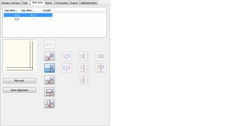
Tab Butt joint
db_ath_easy_sheet_stossausbildung
Sheet edges can be brought together in various ways. The different joint configurations can in each case be implemented variously.
To select the required node use the selection buttons. The active node is highlighted in color. Page forwards or backwards until you reach the required node.
The table shows various joint dimensions of the marked node.
You can edit the dimensions in the cells by direct cell processing. If you click twice consecutively in the cell, the processing mode is activated and you can change the respective value.
Depending on the joint configuration, below the table there are buttons available to define the type of joint. On the buttons the sheet edges are marked with colored figures. The colors in each case match the colored arrows in the dynamic preview. In the counterclockwise direction the "arriving" side is identified in red and the "departing" side in blue.
Apart from the buttons a preview of the selected joint configuration is displayed.
Columns in the joint table
Gap dimension 1 Specifies the gap for the arriving sheet edge (identified with a red 1).
Gap dimension 2 Specifies the gap for the departing sheet edge (identified with a blue 2).
Length Specifies the length of the side fold. This column is not required with all types of joint.
Buttons
Creates an edge joint the same on both sides.
Creates an edge joint, whereby the departing end is covered.
Creates an edge joint, whereby the arriving end is covered.
Creates an edge joint, whereby the departing end is folded towards the inside.
Creates an edge joint, whereby the arriving end is folded towards the inside.
Creates an edge joint, whereby the departing end has an additional cant. This type of joint can only be selected for composite panels.
Creates an edge joint, whereby the arriving end has an additional cant. This type of joint can only be selected for composite panels.
Creates an orthogonal surface joint.
Creates a surface joint with a fold.
Creates a surface joint with a fold.
Opens the current joint configuration.
Creates a flush planar joint.
Creates a planar joint with a fold at both ends.
Creates a mitered planar joint.
Creates a parallel planar joint, whereby the departing end is the major member.
Creates a parallel planar joint, whereby the arriving end is the major member.
Mirrored Copies the current joint configuration with mirrored symmetry on the next node in the counterclockwise direction.
ath_easy_sheet_stoss_spiegelgleich
Joint with mirrored symmetry
Same alignment Copies the current joint configuration with directional symmetry on the next node in the counterclockwise direction.
ath_easy_sheet_stoss_richtungsgleich
Joint with directional symmetry
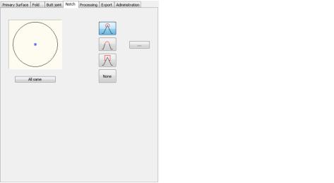
Tab Notch
db_ath_easy_sheet_freistellung
When several surfaces meet, notch processes may be necessary to prevent sheet deformation. Here you can describe given tool shapes by their parameters and assign single surface nodes.
To select the required surface node use the selection buttons. The active surface node is highlighted in color. Page forwards or backwards through the surface nodes until you reach the one you want.
Creates a circular notch on the active surface node.
Creates a notch in the shape of a circular section on the active surface node.
Creates a rectangular notch on the active surface node.
None Creates no notch on the active surface node.
[...] Opens the Dialog box Outline, where you can define the outline of the notch. You will find further information on this in the section Outline.
All equal Applies the setting of the current surface node to all other surface nodes.
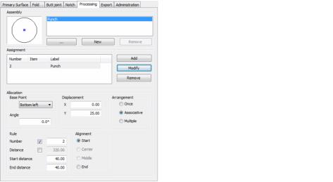
Tab Processing
db_ath_easy_sheet_bearbeitung
Here you can define or select assemblies (= one or several processes) and assign the surfaces of the sheet singly or using distribution rules.
To select the required sheet surface use the selection buttons. The active surface is highlighted in color. Page forwards or backwards until you reach the appropriate surface.
Dialog box section Assembly
db_ath_easy_sheet_bearbeitung_baugruppe
The list shows all available processing assemblies. The marked assembly is shown in the preview adjacent to the list. A circular-shaped process is initialized here during the first start.
[...] Opens the Dialog box Process manager where you can change the marked processing assembly; you can either change the properties of the present process or select a different one to replace it. You will find further information on this in the Chapter Process manager.
New Creates a new processing assembly. The properties of the previously marked assembly are accepted here.
Remove Deletes the marked processing assembly from the list. You can only remove unreferenced processes.
Dialog box section Assignment
db_ath_easy_sheet_bearbeitung_liste
The assignment list shows the processing assemblies which are assigned to the current surface. The number of processes arises from the distribution. You can select the processes in the list in order to change their spacing or distribution rules. When you click a process with the right mouse key, a context menu appears with the following options:
Remove process Removes the selected process from the list.
Remove whole list Removes all processes from the list.
Add Accepts the processing assembly from the assemblies list into the assignment list. The process is placed on the current sheet surface depending on the selected distribution (once, associative or multiple).
Modify Uses the selected distribution on the process marked in the assignment list.
Processes are written as "References" in the area and can therefore also be entered many times. Here, the type of the arrangement (single, associative or multiple) is not important. If the referenced process changes, the "references" also change!
Remove Removes the selected process from the assignment list. This function is identical to the Remove process function in the context menu.
Dialog box section Distribution
db_ath_easy_sheet_bearbeitung_definition
Base point
Defines the reference point for the process on the selected sheet surface, e.g. Top right.
The sheet surface is always viewed from outside.
Displacement
Displaces the base point of the process. Enter the X and Y coordinates in the appropriate input fields. Since a process can also be applied many times in a straight line, a line is displayed in the preview. The coordinates refer to the base point which you can select from the list.
Angle
Defines the angle of the process. The rotation occurs in the counterclockwise direction.
Dialog box section Arrangement
Single Arranges the processes once at the defined base point on the current surface.
Associative Arranges processes regularly, according to the defined distribution, on a straight processing line on the current surface. With associative arrangement the dialog box section changes to that you can define the rules for the associative arrangement.
Multiple Arranges processes irregularly, according to the defined distances, on a straight processing line on the current surface. With associative arrangement the dialog box section changes to that you can define the rules for the multiple arrangement.
Associative arrangements
db_ath_easy_sheet_bearbeitung_verteilung
Dialog box section Rule
Number Defines the number of processes.
Distance Defines the spacing between the processes.
Start distance Defines the distance of the process from the start of the sheet surface.
End distance Defines the distance of the process from the end of the sheet surface.
Dialog box section Alignment
Start Sets the starting point of the process series taking into account the starting distance at the start of the sheet surface.
Center Centers an odd number of processes on the surface. The automatic system included prevents the specification of an even number of processes.
Middle Positions an even number of processes centrally on the surface. The automatic system included prevents the specification of an odd number of processes.
End Sets the starting point of the process series taking into account the starting distance at the end of the sheet surface.
Multiple arrangements
db_ath_easy_sheet_bearbeitung_abstaende
Dialog box section Distances
Defines the spacing of the processes. Enter in each case the spacing of the processes in the input field and confirm them to transfer them into the list. With a right click a context menu with further functions appears.
Erase list entry Removes the selected entry from the list.
Remove whole list Removes all entries from the list.
The number of processes is shown in the dialog box section Rule.
Tab Export
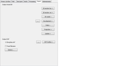
db_ath_easy_sheet_ausgabe
Dialog box section Output AutoCAD
2D section hor Inserts a horizontal Sheet metal section into the current drawing. For this, the dialog box is temporarily closed and an input request appears.
2D section ver Inserts a vertical Sheet metal section into the current drawing. For this, the dialog box is temporarily closed and an input request appears.
3D model Inserts a 3D model into the current drawing. For this, the dialog box is temporarily closed and an input request appears.
Development Inserts a development into the current drawing. For this, the dialog box is temporarily closed and an input request appears.
The inserted sheet development can be edited with a double click.
Dimension and label settings are saved on the relevant sheet.
Folds Consecutively inserts the primary surface and the fold sections of each side into the current drawing. For this, the dialog box is temporarily closed and an input request appears. The insertion of single fold sections is recommended with non-rectangular primary surfaces, because there are no horizontal or vertical sections.
Projection Inserts the projection of the current preview into the current drawing. For this, the dialog box is temporarily closed and an input request appears.
Input request for the insertion commands given above:
Input request
Specify insertion point or [?]:
Use the mouse or enter coordinates to specify the insertion point for the object to be inserted. Once the insertion point has been specified, either the following query appears or the Dialog box ATHENA Sheet processing is reopened.
Specify rotated angle<0>:
Use the mouse or enter an angle to specify the rotation angle of the object to be inserted. This query does not appear with all insertion commands. After specifying the rotation angle the Dialog box ATHENA Sheet processing is reopened.
Update Updates a sheet metal object present in the current drawing. For this, the dialog box is temporarily closed and the following input request appears:
DXF Outline Creates a DXF file with the current DXF settings.
[...] Defines the place of storage for the DXF file. The name of the sheet is used as the file name. If you activate the option Fixed file name, you can also specify a file name here.
Fixed filename Activates or deactivates the issuing of a fixed file name. If the option is activated, the path specification corresponds to a permanently defined saved address.
Options Opens the Dialog box Output DXF, where you can modify the settings for the DXF outline.
Tab Manager
You will find a detailed description of the functions of the manager in the Chapter Management of objects.
End of program
OK Closes the dialog box and saves the current sheet for the duration of the drawing session.
Cancel Terminates the dialog box without saving the changes.