Creates a free semi-finished product from closed outlines. You can use this similar to a Semi-finished product, e.g. material dependent hatching or inserted into various projections.
Valid free semi-finished products always consist of an external outline and optionally several internal contours. The contours must not overlap.
When you execute the command, the Dialog box Free semi-finished product is started where you have the possibilities of defining contours for the semi-finished product.
One quick way of defining a new free semi-finished product is to first select the contours and then call the command. Then you only need to specify the base points and already the contour is displayed in the dialog box.
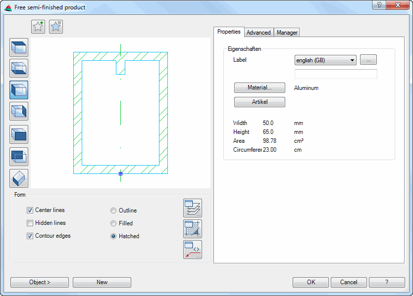
Dialog box Free semi-finished product
In the dialog box you will find on the left side the Display section with the dynamic preview. On the right side you can see the Operating section with the tabs Properties, Advanced and Manager.
db_ath_region
Display section
At the top left there are two buttons for favorites. You will find further information on this in the section Saving and using favorites.
The preview is primarily intended for visual checks and shows the free semi-finished product with the currently set properties.
Additional functions are activated by clicking in the preview with the mouse wheel. You will find further information on this in the section Object preview.
To the left of the preview there are buttons with which you can adjust both the preview and also the insertion into the drawing. You will find further information on this in the section Object views.
Note for insertion into the various views:
• When you insert a free semi-finished product as side elevation from the left or right, only the base point and the rotation angle are interrogated. For further information siehe "Input request for semi-finished product sections".
• If you insert a free semi-finished product as 2D plan view, 2D bottom view, 2D front elevation or 2D rear elevation, the profile length is interrogated on insertion. For further information siehe "Input request for semi-finished product projections".
• The solid is a "known" bar assembly, the name of which consists of the TMP and an incremented number. You will find further information on bar assemblies in the sections Bar assembly manager and Apply bar assembly.
Dialog box section Display
Center lines Switches center lines on or off for a free semi-finished product.
Center lines are only available with symmetrical objects.
Hidden lines Switches the hidden lines on or off.
Contour edges Switches the contour edges for free semi-finished products on or off.
Contour edges are only available with semi-finished products with rounding or tangential transitions.
Outline Creates a free semi-finished product with external outline without infill.
Filled Creates a filled free semi-finished product.
Hatched Creates a free semi-finished product with hatched infill. When you select a material, the material-dependent hatching is used.
Object > Inserts the free semi-finished product into the drawing. For this, the dialog box is temporarily closed and the following appears:
Input request
Specify insertion point or [?]:
Use the mouse or enter coordinates to specify the insertion point of the free semi-finished product.
You can change between different insertion points by repeatedly pressing the Shift+Ctrl keys.
The grips of the relevant profile cross section can be used as insertion points. The insertion point activated by Shift+Ctrl only applies for the duration of the insertion.
With the option ? you call the help.
Specify rotation angle or [?] <0>:
Enter a rotation angle. Press the Enter key to accept the default angle of 0°.
New Selects objects (closed outlines) for the free semi-finished product. For this, the dialog box is temporarily closed and the following appears:
Input request
Select objects:
Selects the contours for the free semi-finished product. You select an external outline and several internal contours. This input request is repeated until you have confirmed the selection of the contours.
Specify the base point for the assembly or [?]:
Determine the base point of the free semi-finished product.
With the option ? you call the help.
Operating section
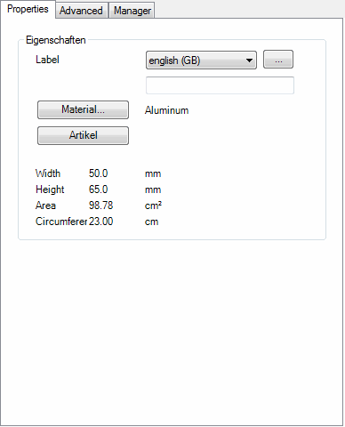
Tab Properties
db_ath_region_eigenschaften
Dialog box section Properties
Labeling Here you can specify a language-dependent label for the object. You select a language from the list and add the appropriate text in the line below. You proceed like this for each language.
[...] Opens the Dialog box Label, where you can conveniently enter the label in several languages.
Item Opens the Dialog box Item, where you can select an item number. You will find a detailed explanation on items in the Chapter Item.
Below the dimensions (total width, total height, area and circumference) of the free semi-finished product are displayed.
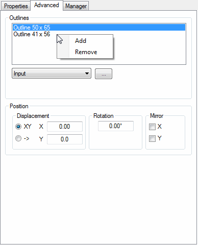
Tab Advanced
db_ath_region_erweitert
Dialog box section Outlines
The list shows the contours of the free semi-finished product. You can select contours here in order to change their properties (position). The selected contour is shown red in the preview.
With a right click in the list a context menu is displayed with various options. Context menu functions:
Add Adds a new outline to the list.
Remove Removes the selected outline from the list.
In the menu field you can select the type of outline. With the button [...] a dialog box opens depending on the selected type of outline or an input request appears. The following types are available:
Outline Opens the Dialog box Outline, where you can define an outline with dimensional entries. You will find further information in the section Outline.
Drilled hole Opens the Dialog box Drilled hole, where you can define a hole as inner contour with dimensional entries. You will find further information in the section Drilled hole.
Input Defines an outline by object selection in the drawing. For this, the dialog box is temporarily closed and the following appears:
Input request
Select objects:
Select an outline for the free semi-finished product (multiple selection is not possible).
Specify the base point for the assembly or [?]:
Determine a base point for the selected outline.
With the option ? you call the help.
Dialog box section Position
Modifies the position of the current outline.
Displacement XY Activates the Cartesian coordinate input for the displacement.
X Defines the absolute X distance between the base point of the current outline and the base point of the free semi-finished product.
Y Defines the absolute Y distance between the base point of the current outline and the base point of the free semi-finished product.
Displacement -> Activates the polar coordinate input for the displacement.
-- Defines the absolute distance between the base point of the current outline and the base point of the free semi-finished product.
< Defines the angle between the base point of the current outline and the base point of the free semi-finished product.
Rotation Defines the rotation angle of the outline.
Mirror X Mirrors the outline in the X direction (not about the X axis!)
Mirror Y Mirrors the outline in the Y direction (not about the Y axis!)
Tab Manager
You will find a detailed description of the functions of the manager in the Chapter Management of objects.
End of program
OK saves the settings made and the dialog box is closed. An input request appears for entry of the free semi-finished product.
Input request
Specify insertion point or [?]:
Use the mouse or enter coordinates to specify the insertion point of the free semi-finished product.
With the option ? you call the help.
Specify rotation angle or [?] <0>:
Enter a rotation angle. Press the Enter key to accept the default angle of 0°.
Cancel closes the dialog box and the settings are discarded.