With this routine you can create the cross section of an infill. An infill may be glass as well as a panel.
The infill structure is defined in a dialog box:
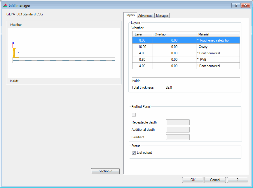
Dialog box Infill manager
In the dialog box you will find on the left side the display section with the preview. On the right side you can see the operating section with the tabs Layers, Advanced and Manager.
db_ath_panel_edit
Display section
At the top left there are two buttons for favorites. You will find further information on this in the section Saving and using favorites.
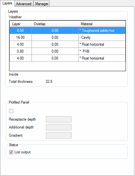
Dialog box section Layers
Displays the preview of the actual infill. The active layer is marked in red. The layer structure is located on the weather side at the top.
Dialog box section Representation
Left Creates the left side of an infill, the right side is interrupted.
Complete Creates a complete infill without interruption.
Right Creates the right side of an infill, the left side is interrupted.
Dialog box section Insert
Length < Defines the overall length of the infill.
Inset < Defines the inset of the infill.
Gasket thickness Defines the thickness of the gasket.
With the buttons Length <, Inset < and Gasket thickness < you can access the appropriate values from the drawing. When you click one of the buttons, the dialog box is temporarily closed and you can select two points. The distance between the points is transferred into the corresponding input field. Alternatively, you can also write the value directly into the corresponding input field.
Mirror Mirrors the infill about its own axis.
Explode Releases the infill into its constituent parts. With a double click the exploded infill can no longer be edited as a whole, but instead only its layers.
The dialog box sections described above of Display, Insert and Output are only shown in the Infill manager when you use the command Infill to insert the defined infill into the drawing. With the definition command Infill manager these sections are not present.
Operating section
Tab Layers
db_ath_panel_edit_schichten
Dialog box section Layers
List Displays the defined layers with their properties from outside (weather side) to the inside (room side). The dimensional properties, such as layer thickness and overlap left/right, can be changed directly in the cells. Further options are available in a context menu which you can activate with a right click.
Context menu options:
Add Creates a new layer. ATHENA inserts the new layer below the marked one (if present). The properties of the marked layer are accepted. Once you have created a new infill and no layer exists yet, you must first write its thickness into the Layer field.
Remove Removes the marked layer from the list.
Properties... Opens the Dialog box Layer, where you can modify the properties of the marked layer. You will find further information on this in the Chapter Membrane.
The tick box activates the function Profiled panel. It is only available when a foldable material has been selected.
Receptacle depth Defines the distance from the sheet edge to the first fold.
Additional depth Defines the thickness of the receptacle.
Slope Defines the gradient of the receptacle.
Dialog box section Status
List output When you activate the tick box List output, the marked layer is output in parts lists. This is indicated in the display with an asterisk (*). The output occurs with the commands Infill list and Infill diagram.
The tick box only has an effect when you use the infill in a 3D construction.
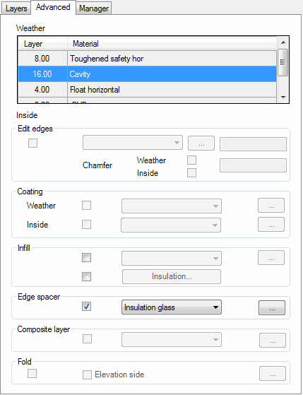
Tab Advanced
db_ath_panel_edit_erweitert
List Lists the existing layers from the weather side to the inside. Here, you can mark a layer to modify its properties.
Dialog box section Edge process
This section is not available for a cavity. Activate the tick box when the layer is to have edge processing. Then select an edge process from the pick list and, where applicable, change the angle in the input field. Activate the tick box chamfer and enter a value into the input field if the layer is to be chamfered. Two additional tick boxes are activated with which you can turn the chamfer at the top and bottom on or off separately. Click the button [...] to create user-defined edge processes; see section Edge processes.
Dialog box section Coating
This section is not available for a cavity. Activate the tick box for the weather side or inside if the layer is to receive a coating. Then select a coating from the pick list. Click the button [...] to create user-defined coatings. The dialog box Coatings is started. The dialog box control is described in the section Dialog box Edge processes.
Dialog box section Infill
The section is not available for a cavity. Activate the tick box when the cavity is to have an infill. Then select an infill from the pick list. Click the button [...] to create user-defined infills. The dialog box Infills is started. The dialog box control is described in the section Dialog box Edge processes. Activate the tick box Insulation when the cavity is to be filled with insulation. Click the button Insulation to change its properties. You will find further information in the Chapter Insulation.
Dialog box section Edge spacer
Activate the tick box to define an edge spacer for the layer. Select insulating glass to use a predefined edge spacer for insulating glass. Click [...] to choose an insulating glass edge spacer in the Dialog box Edge spacer. Select Spacer to use a rectangular edge spacer. Click [...] to adapt the spacer properties. You will find further information in the Chapter Spacer. Choose Profile to use a freely defined profile as the edge spacer. The profile definition occurs in the Dialog box Bar assembly manager. You will find further information in the Chapter Bar assembly manager.
Dialog box section Composite layer
Activate the tick box when you want to insert a composite layer and select a composite layer from the list. Click the button [...] to create user-defined composite layers. The dialog box Composite layers is started. The dialog box control is described in the section Dialog box Edge processes.
Dialog box section Fold
The tick box activates the folding capability of a sheet-metal layer. When you activate the tick box, the Dialog box For object selection is opened, where you can select a fold sequence.
Elevation side Inverts the elevation side of the metal sheet. This function is not available when a sheet with folds is used in an external view (weather side or inside).
You will find a detailed description of the functions of the manager in the Chapter Management of objects.
When you click the OK button, the settings in the dialog box are saved and the input request follows:
Input request
Option Point
Specify insertion point or [Object/?]:
Use the mouse or enter co-ordinates to specify the insertion point for the infill. Select the Option Object to append an infill to one or more existing bar cross-sections. With the option ? you call the help.
Specify rotated angle<0>:
Enter a rotation angle. Press the Enter key to accept the default angle of 0°.
These two input requests are repeated until you press the Enter key to terminate the command.
Option Object
Select first bar cross-section or [Point/?]:
Select an existing bar cross-section to append the infill. Select the Option Point to insert an infill at any point.
Select second bar cross-section or [?]:
Select a further bar cross-section (flush with the one previously selected) to fit the infill between the two bar cross-sections. If you press the Enter key at this point, the infill is positioned with interrupted representation on the first bar cross-section.
These requests are repeated until you press the Enter key to terminate the command.
The infills are inserted on the Infill position of the previous bar cross-section. If none has been defined, an appropriate notice appears in the command line.
The cross sections of the infills, which you insert with this command, are not linked to saved library objects and cannot be updated.
Note
You can label the individual layers retrospectively with the command Parts labeling.