A parts list of the bars is generated with this command. It can be directly inserted into the drawing and optionally copied to the Windows clipboard to insert it into another program, e.g. Excel.
To create a parts list, the parts must have an item number and have been allocated to a job with the Project browser.
In the Dialog box Bar list you can define what is to be written in the parts list.
When you run the command, you may be prompted to update identifiers:
db_ath_tags_update
This happens if you have carried out a common part recognition with the command Assign tags. Identifiers should be updated if dimensional changes have occurred. If in doubt, we recommend that you always update the identifiers, otherwise errors may occur in the BOM.
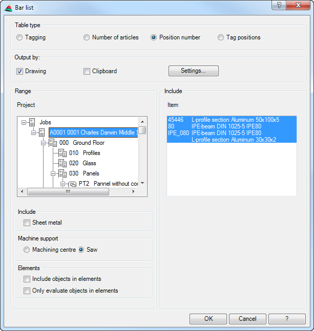
Dialog box Bar list
db_ath_st3d_bar_list
Dialog box section Table type
Tag Creates a parts list in which parts with the same tags are brought together. A prerequisite for this is that you have previously assigned tags. See Assign tags.
Number of articles Creates a parts list in which the selected items are brought together. For example all mullions.
Position number Creates a parts list of the individual positions. The same parts are not brought together.
Tag positions Creates a list of tags with the positions contained in them. A prerequisite for this is that you have previously assigned tags. See Assign tags.
Dialog box section Output
Drawing Generates a list which is inserted into the drawing. Alternatively, an existing list can be updated. An input request follows for inserting the list.
Clipboard Copies the list to the clipboard. As standard, this tick box is deactivated.
Settings ... Opens the Dialog box Table settings, where you can configure the list settings. You will find further information on this in the section Table.
Dialog box section Region
Project Shows the project structure of the drawing. Here, select the job which you want to analyze.
Sheet metal Writes components which contain metal sheet to the parts list.
Machining center Uses the machine support, which was set for the CNC machining center (CMC), for calculating the cutting angle.
Saw Uses the machine support, which was set for the saw, for calculating the cutting angle.
Include objects in elements Also writes bars to the parts list which have been defined in an element.
Only evaluate objects in elements Writes only bars to the parts list which have been defined in an element.
Item Lists bars of the selected job. Here you can select which parts are to be included in the parts list. By holding down Shift or Control (Windows standard) a multiple selection is possible.
End of program
After termination of the dialog box with OK, then, depending on the setting, the bar list is inserted into the drawing and/or copied to the clipboard. After copying to the clipboard, a message appears which you must confirm. With insertion into the drawing, the following appears:
Input request
Specify insertion point or [Replace/?]: Insert the list into the drawing at the desired point or choose the Replace option to update an existing list.
With the option ? you call the help.
Note: This function produces parts lists of bars. CAD-PLAN GmbH can in no way be held liable for the results of this function and any errors and losses arising from it.