Tab ATHENA Model > Group Project > Project browser
Menu:
Modeling > Analyze > Project browser
Toolbar:
ATH Analyze > Project browser
Command input:
ath_project_browser
Manages parts in a project structure.
The project structure is used for the evaluation. For example, you may create parts lists and production drawings and export data.
The project structure is a tree structure. It must contain at least one job. A job can also be subdivided into further partial jobs. The job or partial job is assigned parts in the form of items and collected for evaluation.
You can create the project structure consisting of jobs and partial jobs directly in the project browser. However, since jobs contain further data, it is recommended that you use this Project Manager. You will find further information in the section Project Manager.
When you execute the command, the project is displayed as a palette. General properties and functions of palettes are not discussed here. For more information, refer to the AutoCAD documentation.
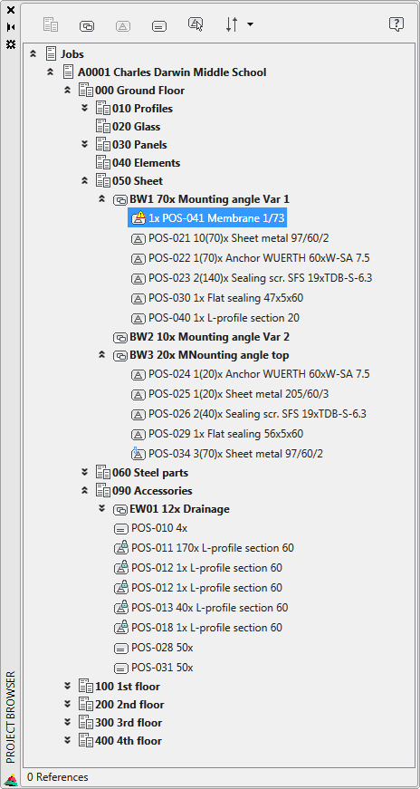
Palette Project browser
db_ath_project_browser
Elements of the Project Structure in the Project Browser
Job
The job is the first node in the tree structure of the project browser. A job can contain partial orders as well as groups and items.
Theoretically, you can create several orders in one drawing. However, this is not recommended, as each job usually represents an independent project.
Job part
A partial job is part of a job or another partial job. The project structure can be interconnected to any degree. However, the more the structure is interconnected, the more confusing it becomes.
A partial job can contain further partial jobs as well as groups and positions.
Group
A group is usually a combination of several positions. In contrast to the job/partial job, you must specify a quantity for the group. The number of pieces of the group components is multiplied by the number of pieces of the group. Example: The group mounting bracket is required 70x for partial job and consists of a plate, an anchor and two sealing screws. This means that 70 plates, 70 anchors and 140 sealing screws are required. A group can contain additional groups as well as positions.
Position
An item is a physical component within the project structure. There are different types of positions.
Drawing position
This is a position associated with a drawing object.
Permitted objects for drawing items are:
• ATHENA ARX objects, other than axle lines and labels.
• AutoCAD solids.
• Blocks to which Assign block label information was previously attached with the command.
Drawing position, incomplete
A position that is linked to a drawing object but cannot be evaluated because information is missing (e.g. length).
Drawing position, referenced
A position that is linked to another drawing position. All properties except the number of pieces are taken from the referenced drawing position.
Drawing position, not detachable
A position that is linked to a drawing object and cannot be detached from it, as it would result in a loss of information. Example: 3D rods.
Free position
A position that has no relation to an object in the drawing, i.e. a position that is defined only by properties, without a graphical representation.
Free position, referenced
A position that is linked to another free position. All properties except the quantity are taken from the referenced free position.
A right click within the project structure of the project browser opens a context menu. The options displayed in the context menu are different and depend on the object clicked in the browser.
Creates a partial job in the project browser. This option is only available if you are in the project structure for a job or partial job.
When you add a partial job the Dialog box Add is displayed where you can enter the most important data for the partial job.
You can define additional data for orders and partial orders in the Dialog box Project Manager. You will find further information on this in the section Project Manager.
Creates a group in the project browser. This option is available only when you are in the Project Structure on a job, partial job, or group.
When you add a group, the Dialog box Group is displayed where you can enter its properties.
New positions - drawing objects
Creates positions by selecting drawing objects. This option is available only when you are in the Project Structure on a job, partial job, or group. The following procedure is used:
Input request
Select objects:
Select the objects that you want to copy to the project structure as items. Press the Enter key to complete the object selection.
The drawing positions are inserted in the selected branch of the project structure.
Objects that already exist in the project structure and projections of these cannot be selected. Therefore, duplicates in the job are excluded.
Objects that are not allowed (lines, circles, hatches, etc.) can be selected, but are not included in the project structure. If necessary, such objects must be combined into a block and given further information (Assign block label) so that they can be used as drawing items.
Creates a free position in the project browser. This option is available only when you are in the Project Structure on a job, partial job, or group.
If you add a free position, the Dialog box Position will be displayed where you can set its properties.
Find drawing object in job Jumps to the drawing position in the job that is linked to the selected drawing object and marks it.
Input request
Select object:
Select the object in the drawing whose linked drawing position you want to display in the project structure.
Change sorting Changes the display order in the project structure.
You can either display the partial jobs at the top (partial job, group, item) or at the bottom (item, group, partial job).
New positions - selection filter: Bars Creates positions by selecting drawing objects. Only rods are transferred to the project structure. All other objects are filtered out.
This option is available only when you are in the Project Structure on a job, partial job, or group. The following procedure is used:
Input request
Select objects:
Select the objects that you want to copy to the project structure as items. Press the Enter key to complete the object selection.
New positions - selection filter: Infills Creates positions by selecting drawing objects. Only fillings are transferred to the project structure. All other objects are filtered out.
This option is available only when you are in the Project Structure on a job, partial job, or group. The following procedure is used:
Input request
Select objects:
Select the objects that you want to copy to the project structure as items. Press the Enter key to complete the object selection.
Navigate to the drawing object Zooms to the linked drawing objects of the selected position. The drawing objects are displayed and selected at the highest magnification in the center of the view.
Append drawing object Adds a drawing object to an existing position. The drawing object must be identical to the position. Example: A hexagon bolt ISO 4014 M8x30 is already present in the project structure and you want to add further representations of it.
Jump to referenced object Jumps to the referenced position in the project structure. This is necessary, for example, if you want to change certain properties of the position, which is not possible with references, but only with the referenced position.
Detach position Removes the link between the selected position and the drawing object.
Solving the problem is only possible if it does not lead to a loss of information. Some objects (e.g. 3D rods) cannot be solved.
Non-releasable positions are symbolized by a lock in the icon.
Remove Removes the selected object from the project structure of the project browser. Orders, partial orders and groups can only be removed if they are empty, i.e. do not contain any items or other elements.
Cut Transfers the selected objects to the clipboard. The objects can then be inserted in another area of the project structure. The selected objects are only removed after they have been inserted.
Copy Copies the selected positions to the clipboard. The items can then be inserted or referenced in another area of the project structure.
Insert Pastes the contents of the clipboard into the selected area of the project structure (job, partial job or group).
Insert as reference Pastes the contents of the clipboard as a reference to the original object in the selected area of the project structure (job, partial job or group).
Bar list Generates a list of the bars. The objects in the selected area of the project structure are evaluated. The Dialog box Bar list is displayed for further restriction of the objects to be evaluated and for list configuration. You will find further information in the section Bar list.
Infill list Produces a list of the infills The objects in the selected area of the project structure are evaluated. The Dialog box Infill list is displayed for further restriction of the objects to be evaluated and for list configuration. You will find further information in the section Infill list.
Assembly list Generates a list of the assemblies. The objects in the selected area of the project structure are evaluated. The Dialog box List assembly is displayed for further restriction of the objects to be evaluated and for list configuration. You will find further information in the section Assembly list.
Profiled sheet list Generates a list of the profiled sheets. The objects in the selected area of the project structure are evaluated. The Dialog box List profiled sheet is displayed for further restriction of the objects to be evaluated and for list configuration. You will find further information in the section Profiled sheet list.
List insulation / seal Creates a list of insulation and sealing materials. The objects in the selected area of the project structure are evaluated. The Dialog box List insulation / seal is displayed for further restriction of the objects to be evaluated and for list configuration. You will find further information in the section List insulation / seal.
List free position Generates a list of the free positions. The objects in the selected area of the project structure are evaluated. The Dialog box List free position is displayed for further restriction of the objects to be evaluated and for list configuration. You will find further information in the section List free position.
List pipe element Generates a list of the pipe elements. The objects in the selected area of the project structure are evaluated. The Dialog box List pipe element is displayed for further restriction of the objects to be evaluated and for list configuration. You will find further information in the section List pipe element.
List sheet Generates a list of the folded sheets. The objects in the selected area of the project structure are evaluated. The Dialog box List sheet is displayed for further restriction of the objects to be evaluated and for list configuration. You will find further information in the section List sheet.
IFC Creates an IFC file. The objects in the selected area of the project structure are evaluated. The Dialog box Export IFC is displayed for additional settings. You will find further information in the section Export IFC.
XML (ERP) Creates an XML file for ERP systems. The objects in the selected area of the project structure are evaluated. You will find further information in the section Export ERP.
SAT Creates a SAT file. The objects in the selected area of the project structure are evaluated. The Dialog box Export SAT is displayed for additional settings. You will find further information in the section Export SAT.
NCW Creates an NCW file. The objects in the selected area of the project structure are evaluated. The Dialog box Export NCW is displayed for additional settings. You will find further information in the section Export NCW.
Properties Displays the properties of the selected object in the Palette Object properties. Most properties are informative. Some properties can be changed there.
Important notes for working with the project browser:
• Effects when cutting (CTRL+X) drawing objects: If you cut out drawing objects (CTRL+X), the corresponding positions in the browser are permanently deleted and are not restored even when you insert them (CTRL+V).
• Project rods without drawing assignment: Project rods to which no drawing object is assigned (e.g. solved member projections) are not taken into account by "Assign tags" during the recognition of identical parts.
• Profile cross-sections without length: Profile cross-sections (for example of standard profiles) that are inserted as positions in the browser do not yet have a length. Page views you create with "Projection objects" are automatically 50 mm long. It is therefore recommended to first enter a length in the position properties!
• Blocks Blocks can only be included in the project structure after they have been assigned with "Assign block label" specific information.