ATH Drawing > Grid division ATHENA Functions > Grid division
Command input:
ath_grid
Divides up an area with a rectangular grid, for example, to produce a placement plan. The grid layout is inserted in the defined area, optionally with labeling and dimensioning.
Additionally, a list as well as the outlines, also fully dimensioned and positioned, can be inserted into the drawing.
When you start the command, the following appears:
Input request
Specify point in the area or [Objects/?]: <Objects>:
Specify a point within the area which is to be divided with a grid.
Select the outlines which are to be divided with a grid. Inner outlines are detected as islands and are left out.
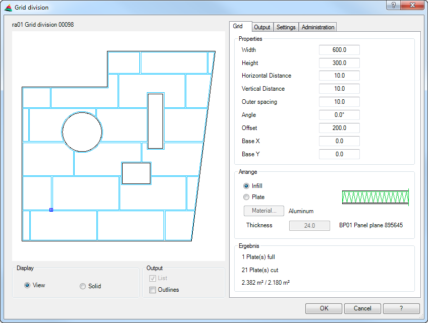
Once you have terminated the input request, the Dialog box Grid Division is opened, where you can carry out settings for the grid division.
Dialog box Grid Division
On the left side the dialog box contains a preview of the grid division. The preview is used as a visual check. Additional functions are activated by clicking in the preview with the mouse wheel. You will find further information on this in the section Object preview. On the right side of the dialog box there is the operating section with the tabs:
Elevation Represents the grid layout panels as a two-dimensional view.
Solids Displays the profiles of the grid division plan as 3D-solids.
Dialog box section Output
List Activates or deactivates the list output.
Outlines Activates or deactivates the outlines output.
Operating section
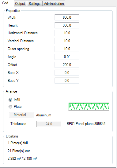
Tab Grid
db_ath_grid_raster
Dialog box section Properties
Width Defines the width of a plate.
Height Defines the height of a plate.
Horizontal distance Defines the distance between the horizontal plates.
Vertical distance Defines the distance between the vertical plates.
Outer spacing Defines the spacing between the plates and the selected outline.
Angle Defines the angle of the plate alignment.
Offset Defines the offset between the vertical plates.
An angle of 0° gives a horizontal offset, an angle of 90° a vertical one.
Base X Displaces the base point of the first plate in the X direction.
Base Y Displaces the base point of the first plate in the Y direction.
Dialog box section Arrange
Infill Defines a stored fill (e.g. a panel) for the grid layout panels. When you activate this option, the dialog box Object selection is displayed, where you can select an infill.
Plate Defines the grid layout panels by material and thickness.
Thickness Defines the panel thickness. The input field is only available if you use the option Plate.
Dialog box section Result
Shows how many complete and cut plates are needed for the selected outline. Furthermore, the area of the selected outline and the total area of all plates are shown.
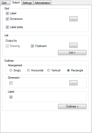
Tab Output
db_ath_grid_ausgabe
Dialog box section Grid
Labeling Provides the grid layout heading. The heading may be configured under the Tab Settings.
Label plate Labels the grid layout panels. You may configure the panel label at the Tab Settings.
Dialog box section List
Drawing Generates a list which is inserted into the drawing. Alternatively, an existing list can be updated. An input request follows for inserting the list.
Clipboard Copies the list to the clipboard. As standard, this tick box is deactivated.
[...] Opens the Dialog box Table settings, where you can configure the list settings. You will find further information on this in the section Table.
List > Inserts the list into the drawing. The dialog box is terminated and then follows:
Input request
Specify insertion point or [?]:
Define the insertion point of the list.
With the option ? you call the help.
Dialog box section Outlines
Singly Arranges the plates singly during the output. You must specify an insertion point for each plate.
Horizontal Arranges the plates horizontally during the output. You only need to specify one insertion point. The base point of the insertion is the lower left corner of the first plate; all other plates are arranged adjacently horizontally to the right.
Vertical Arranges the plates vertically during the output. You only need to specify one insertion point. The base point of the insertion is the lower left corner of the first plate; all other plates are arranged vertically below it.
Rectangle Arranges the plates rectangular during the output. You only need to specify one insertion point. The base point of the insertion is the lower left corner of the first plate; all other plates are arranged rectangular to the right and below.
Dimensions Enables the dimensioning of the individual contours.
Labeling Labels the individual contours. You may configure the contour label at the Tab Settings.
Outlines > Inserts the contours into the drawing according to the specified settings. The dialog box is terminated and then follows:
Input request
Specify insertion point or [?]:
Define the insertion point of the list.
With the option ? you call the help.
This prompt is repeated until you have placed all contours in the drawing.
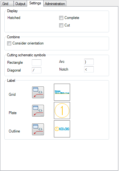
Tab Settings
db_ath_grid_settings
Dialog box section Display
Hatched Complete Fills all complete plates with a hatching pattern.
Cut Fills all plates that were cut with a hatching pattern.
Dialog box section Combine
Consider orientation Uses different position numbers for the same parts when they are aligned differently.
Dialog box section Cutting schematic symbols
Rectangle Defines the identifier for rectangular plates.
Arc Defines the identifier for plates with an arc.
Diagonal Defines the identifier for diagonally cut plates.
Notch Defines the identifier for plates with a notch.
Dialog box section Labeling
The tick box activates or deactivates the labeling of the output.
Labeling Opens the Dialog box Label, where you can modify the settings for the position label. You will find further information on this in the Chapter Labeling.
The current settings for the dimension style, text height and layer are displayed for information and can be changed by clicking the Format button.
Format Opens the Dialog box Leader, where you can format the label symbols. You will find further information in the Chapter Leader, Section Symbol/frame.
Dialog box section Output
Include full plates Defines that full plates are also listed in the table output
Dialog box section Column
Drawing Generates a list which is inserted into the drawing. Alternatively, an existing list can be updated. An input request follows for inserting the list.
Clipboard Copies the list to the clipboard. As standard, this tick box is deactivated.
Settings ... Opens the Dialog box Table settings, where you can configure the list settings. You will find further information on this in the section Table.
Rectangle Defines the identifier for rectangular plates.
Diagonal Defines the identifier for diagonally cut plates.
Arc Defines the identifier for plates with an arc.
Notch Defines the identifier for plates with a notch.
Dialog box section Text
Text height Defines the text height of the list. The current dimension figure height is used as the default.
Default Restores the default text height of the list.
Dialog box section Output
Include full plates Also outputs full plates as outline.
Dialog box section Create
Hatch Hatches the outlines for the output. The hatching settings of the object are used for the hatching.
In each case this opens the Dialog box Label where you can influence the label options for the single components. You will find further information on this in the Chapter Labeling.
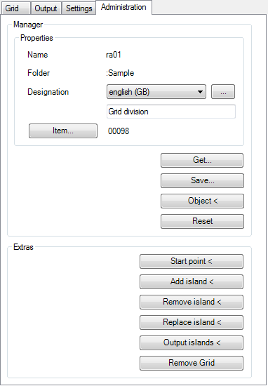
Tab Administration
db_ath_grid_verwaltung
Dialog box section Manager
You will find a detailed description of the general functions of the manager in the Chapter Management of objects.
Dialog box section Extras
Start point < Defines a new start point for the grid division. For this, the dialog box is temporarily closed and the following appears:
Input request
Specify start point or [?]:
Use the mouse or enter coordinates to specify the start point for the grid division.
With the option ? you call the help.
Add island < Defines a further inner contour in the grid division. For this, the dialog box is temporarily closed and the following appears:
Input request
Select outline or [?]:
Select a further inner contour for the grid division. You can only choose one outline. If you would like to supplement further outlines, the call has to be repeated.
With the option ? you call the help.
Remove island < Removes an island from the grid division.
Input request
Specify point in the area or [?]:
Click with the cursor in the island area that you want to remove.
Select outline or [?]:
Choose the new outline for the island.
With the option ? you call the help.
Replace island < Swaps the contour of an existing island for a new one. For this, the dialog box is temporarily closed and the following appears:
Input request
Specify point in the area or [?]:
Click with the cursor in the island area whose contour is to be swapped.
Select outline or [?]:
Choose the new outline for the island.
With the option ? you call the help.
Output islands < Draws the islands as new outlines. This may be necessary if you have deleted the islands in the meantime. There is no indication in which the islands are redrawn in the background.
Remove grid Removes the grid from the drawing. A confirmation query appears. If you answer this with Yes, the dialog box is closed and the grid removed.
The button Remove Grid is only enabled when editing existing grid divisions.
End of program
When you terminate the program with OK, the grid division and, if necessary, the list and outlines are created in the drawing.
The grid division is inserted into the drawing as an object.
Evaluation of the panels
To perform a list evaluation of the panels (lists), you must assign the grid layout to an order. You may then output a list of panels. The following functions are required for this: