When you click on the Default settings ... button in the Dialog box ATHENA options, ATHENA starts a dialog box where you can carry out the presettings for various functions.
Dialog box Presettings
db_ath_optionen_einstellung
Drop-down menu Objects
db_ath_optionen_voreinstellung-objekte
In the upper pick list you can define in which units the values of this dialog box section are displayed. You have a choice between millimeters and inches.
Distance of coating line Here you define the default distance between the sheet metal section and the coating line.
Thickness of sheet metal section Here you define the default sheet thickness for the command Sheet metal section.
Overlap of center lines default Here you define the default center line overlap of center lines, which are created with the commands Standard Part, Semi-finished product, Center lines and Axis, for new drawings.
This setting only affects template files which have not been generated with ATHENA, e.g. acad.dwt, acadiso.dwt...!
Overlap of center lines current dwg. Here you define the default center line overlap of center lines, which are created with the commands Standard Part, Semi-finished product, Center lines and Axis, for current drawings.
Distance of interrupt lines Here you define the default gap between the interrupt lines which are created by the command Interruption.
Thickness of insulation Here you define the default thickness of the thermal insulation which is created with the command Insulation.
Membrane thickness Here you define the default thickness of the membrane which is created with the command Membrane.
Drop-down menu Frame elements
db_ath_optionen_voreinstellung-einsatzelemente
Dialog box section Display
Here you define how CAD positions are inserted into the drawing with the command Frame element.
Elevation Generates a CAD position as 2D elevation in the drawing.
Solids Generates a CAD position as a three-dimensional solid in the drawing.
You can subsequently change the view of the inserted CAD positions with the command Display modes.
Dialog box section Field symbol
DIN/ISO/EN Opening symbols for frame elements are generated such that the opening points to the hinged side and the tip points to the handle side.
USA Opening symbols for frame elements are generated such that the opening points to the handle side and the tip points to the hinged side.
Dialog box section Temporary import files
Remove Temporary import files are deleted. This is the normal case.
Save Temporary import files are saved. If there are problems during import, you can activate this setting and send the import file to Technical Support for checking.
Drop-down menu Bars
db_ath_optionen_voreinstellung-3d_staebe
Dialog box section Mark bar without solid
Controls the marking for bars without solid (Dialog box Display modes, profile representation = axis):
• For null bars a green directional cone is displayed.
• For bars in axial representation which have not yet been assigned to any job, a green directional cone is shown.
• For bars in axial representation which have been assigned to a job, the position number is shown.
Variants of bar marking.
On Displays the marking.
Off Displays no marking.
Diameter/text height Determines the absolute size of the marking.
After switching on and off or changing the size of the marking, you have to regenerate the drawing so that the change is visible.
Dialog box section Machine support
Machining center As standard, uses the machine support, which was set for the CNC machining center (CMC), for calculating the cutting angle.
Saw As standard, uses the machine support, which was set for the saw, for calculating the cutting angle.
Development segmentation These settings affect the calculation of the development of the round tubes. The default values are suitable for tubes up to a diameter of approx. 200 mm. With larger diameters you should enlarge the arc length.
Arc length Specifies the arc length for which a segment is inserted for segmented development.
Minimum number of segments Specifies the minimum number of segments.
Drop-down menu Infills
db_ath_optionen_voreinstellung-3d_fuellungen
Dialog box section Determine infill
These settings act on the automatic infill determination. You will find further information in the section Determine infill.
Precision of position Inaccuracies in the offset of infill positions are ignored up to the stated value. Larger inaccuracies are displayed by the message: Conflict - infill positions of boundary objects.
Precision of clamping Inaccuracies in the clamping thicknesses of the infill positions are ignored up to the stated value. Larger inaccuracies are displayed by the message: Conflict - clamping of boundary objects.
These settings act on the section generation. You will find further information on this in the section Generating a section from 3D.
Dialog box section Insert in
WCS Inserts the generated section in the XY plane of the World Coordinate System.
UCS Inserts the generated section in the XY plane of the current User Coordinate System.
Section plane Inserts the generated section in the specified sectional plane.
Associative Generates associative sections. The section can therefore be updated for geometrical changes.
Labeling objects Labels the sectioned objects. In the section profiles are labeled with their item number.
Dialog box section Include visible edges
Maximum distance Specifies the maximum distance to the sectional plane in which visible edges of the solid of unsectioned bars and infills are displayed in section. E.g.: You are generating a horizontal section through two mullions. If a transom is located less than 100 mm below the sectional plane, its visible edges are shown in section.
Dialog box section Mark section plane
Layer The tick box activates the sectional plane marking. In the pull-down menu you can select a layer for marking.
Enlarge by Specifies the enlargement of the sectional plane marking.
The sectional plane is identified by a region. The size of the region corresponds to the enclosing rectangle of the sectioned objects plus the enlargement. With associative sections the sectional plane marking cannot be turned off.
Dialog box section Infills
Interrupt display Generates infills with interrupted display (right and left section instead of complete infill).
Drop-down menu Analyse axis model
db_ath_optionen_voreinstellung-3d_achsanalyse
Length mark weather side Specifies the length of the red lines which mark the weather side during the analysis of axis models.
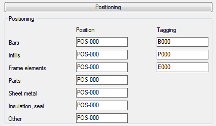
Drop-down menu Positioning
db_ath_optionen_voreinstellung_3d_positionierung
Position: Defines the position number prefixes that will be assigned to the different elements under the nickname of the project. Assigning an order with the Project browser parts from the drawing will automatically give you a position ID with the appropriate prefix. The numbers will be incremented.
Tagging: Defines the prefixes that are assigned to the individual parts in common-part identification. If you select the parts Assign tags, these numbers will be incremented. You will find further information in the section Assign tags.
Dialog box section Format
Defines default values for job data and parts for Positions.